
Abstract: In order to improve the design and manufacturing scheme of the front lamp detection module, the design difficulties of the front lamp processing and detection module were analyzed, the structural design scheme of the module was proposed and the front side rough machining layout of the front lamp module was equipped. , Carried out secondary roughing, semi-finishing and aging treatment for the front light module, and designed the module manufacturing process and CNC machining process. The application test shows that the design scheme of the headlight module has high reliability, and has no color difference with the adjacent module connection surface, good matching degree, and supports the interchangeability between the actual headlight and the module. It can be used for similar products. The design and manufacture provide a reference basis.
Key Words: headlight module; Main Model Checker; Roughing; Semi-Finishing; Finishing Services
#1 Structure And Testing Standard Of Headlight Module
The position of the front light module in the main model of the car is quite special, and its position is not only connected with the fender, but also connected with the front bumper and the hood module [1]. Install this module on the car master model frame to show the state of the headlights in the car body. If the real car lights and connectors are interchanged, the position of each hole, the peripheral contour, the surface difference of the car lights, the smoothness and the gap between parts can be detected, the lighting conditions of the car lights can be observed, and the overall visual effect can be felt[2 ], so the front light module structure is called the front light detection module in the main vehicle model inspection tool. In order to explore the structural characteristics of the headlight module, the design method of the headlight detection module is discussed. The structure of the headlight module is shown in Figure 1.
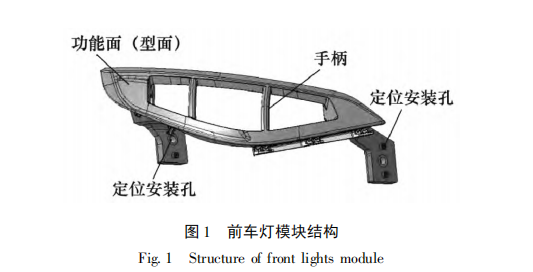
The module detection function is basically consistent with the headlight surface data provided by the user. The module accuracy detection standard value is set as follows: the surface of the headlight module is clean and bright, the direction of the knife lines between the connecting modules must be the same, there is no color difference at the interface, and there is no air hole. Set the detection standard for this parameter: the surface roughness of the module should not be greater than 0.8; the deviation of the surface profile should not be greater than ±0.1 mm; the gap between adjacent modules should be kept within ±0.1 mm; the deviation of the line profile should be within the range of ±0.1 mm Inside; the position deviation of the positioning installation hole is less than 0.1 mm.
#2 The Design Of Front Light Detection Module
1. Difficulties in the design of front lamp processing and detection modules
Since the headlight module is a hollow structure, the rigidity is relatively small, and the value of the edge thickness parameter is small, and deformation problems are prone to occur during processing. Therefore, the processing technology of this module needs to cooperate with parameter detection. According to the deformation detection results, the corresponding heat treatment is adopted to achieve the purpose of controlling the deformation of the model.
Considering that most of the headlight modules are milled from forged aluminum blanks, it is necessary to change the clamping position many times to complete the processing of the reverse and front sides [3]. In order to meet this design requirement, it is necessary to ensure the consistency of the processing technology benchmark for changing the clamping position, and carry out finishing treatment according to the test results.
Module processing materials have high elastic modulus and low melting point, and are prone to built-up edge during processing, which reduces the quality of the workpiece [4]. In order to meet the requirements of processing quality standards, by controlling the temperature of the workshop, the processing temperature is detected by the detection device, and the instantaneous temperature is properly adjusted according to the monitoring results so that it is not greater than 30°C, so as to avoid deformation of the processed materials .
The shape of the module is irregular, and the processing standard value of the wall thickness in many places is too small, which increases the difficulty of processing, and the clamping is prone to deformation during the processing [5]. Therefore, it is required that the designed module must be equipped with multiple auxiliary supports to minimize the processing deformation quantity.
2. Module structure design
Two operating handles are arranged in the structure of the front light module. In order to meet the requirements of the overall appearance process and handle strength, this design model seamlessly connects them with the main body to create an integrated device. The selected processing technology is the clamping process (the front side is processed while the back side is hoisted), and the two assembly surfaces with different heights are hoisted to improve the structural rigidity. Additionally, 2 small hoisting planes have been added to this structure as rigidity enhancement aids.
In order to meet the processing standards of automotive lamp modules, it is necessary to optimize the design of the module processing plan, strictly follow the processing benchmarks, and arrange the processing plan reasonably [6]. Aiming at the processing requirements of the headlight module, a number of important processing methods are designed, including roughing and semi-finishing.
3. Rough machining arrangement on the reverse side of the front light module
Module roughing is an important process in the machining process, and the deformation of the module needs to be strictly controlled. Back roughing is the first step in the module roughing operation, and the corner of the blank is used as the initial reference for roughing. Considering the control of material consumption, two sets of hoisting bosses are left for it after thickening on the reverse side, one set is used for oblique standing assistance, and the other is used for standing upright assistance. Due to the problem that the module is prone to deformation during processing, the process plan for this processing is to carry out roughing in two times. The first roughing is the back roughing with a margin of 2.5 mm. The second roughing adopts the front roughing method, and the tool used for lifting adopts the method of inclined auxiliary lifting boss, and the other set of lifting bosses are used as front semi-finishing tools to reduce the height of the blank.
4. Rough processing arrangement for the front of the front light module
After the back roughing is completed, the front roughing treatment of the model is started, and the processing standard is the same as that of the back roughing, and the processing tool used is the oblique auxiliary boss. Considering the need for subsequent construction clamping and tooling to complete the processing operation, the erection auxiliary tool is not used here, but is reserved. At the same time, the lifting hole is drilled according to the processing requirements. After the front roughening is completed, a margin of 2. 5 mm is also reserved. Subsequent semi-finishing and the second frontal roughing shall be based on the regular cubic datum boss.
5. Arrangements for the second roughing, semi-finishing and aging treatment of the front light module
(1) Aging treatment
The aging treatment of the module is divided into three links, which are natural aging treatment, artificial aging treatment and natural aging treatment. The first natural aging treatment took place at the end of the first roughing, and the duration of the treatment was about 7 days, which mainly played the role of eliminating residual internal stress in the module. The artificial aging treatment takes place after the second roughing, and the second natural aging treatment takes place after the semi-finishing.
(2) The second roughing
After the first natural aging treatment is completed, the second rough machining is carried out. The reverse side is still processed first, and the tool setting datum is laid as the square datum boss, and the contour datum boss and the front auxiliary hoisting boss are used for processing. mm margin. The second roughing method is adopted on the front surface of the model, the tool setting reference remains unchanged, and the auxiliary lifting boss on the front surface with the same height is used as the roughing tool to mill out the oblique auxiliary lifting boss located on the front surface of the model and rough it. Leave a margin of 1 mm when finished.
(3) Semi-finishing
Use artificial aging to treat the roughing module to reduce the residual internal stress in the structure, and then start semi-finishing. Take the reverse side first, and take the reference boss as the processing standard, and mill off the erect lifting boss located on the reverse side. The semi-finishing of the reverse side of the module is shown in Figure 2.
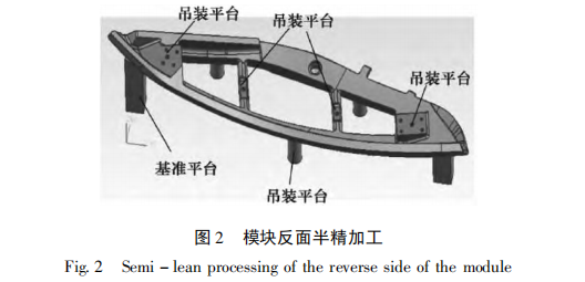
During the processing, the 4 hoisting planes are taken as the primary processing object, and the hoisting holes are drilled after milling out. According to the theoretical parameter standards, the height of the 4 hoisting planes is strictly controlled to be consistent. The margin after the implementation of this machining process is set to 0.1 mm. The front of the module is semi-finished, as shown in Figure 3.
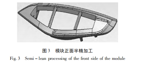
At the center of the front square datum boss, set the origin and mill out the front boss during machining. In order to ensure the processing quality, secondary processing is carried out. During the first milling operation, the back knife eats 0.6 mm, and the processing is completed according to this standard. Turn on the second milling operation, and the index parameters are reduced by 0.3 mm; the second operation is reserved for the remainder, all 0.2 mm.
#3 Manufacturing Technology And CNC Machining Of Headlights
1. Manufacturing process of headlights
- Step 1: cutting. The blanking specification of this process is 630 mm × 210 mm × 130 mm, and a margin is required, and the margin on one side is 5 mm.
- Step 2: open rough once. The reverse side is roughed first, and then the front side is roughed. A margin is reserved for roughing on both sides, and the parameter value is 2. 5 mm.
- Step 3: heat treatment. The natural aging method is used to process the modules after a roughing operation.
- Step 4: Second roughening. The reverse side is roughed first, and then the front side is roughed. Allowance is reserved for roughing on both sides, and the parameter value is 1 mm.
- Step 5: heat treatment. The artificial aging method is used to process the modules after the secondary roughing operation is completed.
- Step 6: Semi-finish milling. Roughing is performed on the reverse side first, and then semi-finish milling is performed on the front side. There is a margin on both sides of the semi-finish milling process and the parameter value is 0.2 mm.
- Step 7: heat treatment, etc. The module after the semi-finishing milling operation is processed by natural aging method. Step eight: actual measurement. Use the three-coordinate measurement method to test the parameters of each index and record the relevant data.
- Step 8: fine milling and so on. Each functional surface of the module is fine milled.
- Step 9: Probing. The third is to use the three-coordinate measurement method to test the parameters of each index and record the relevant data.
2. CNC machining process design for headlight manufacturing
The cemented carbide tool of model D25R1 is selected as the processing tool, and the cavity milling process is used to complete the first roughing on the reverse side of the module. Among them, the various processing parameters are set as a margin of 2.5 mm, a feed rate of 2000 mm/min, and a spindle speed of 2500 r/min. The first roughing of the front is the same as the design scheme of this process. The twist drill model Z5 is selected as the processing tool, and the hoisting hole drilling process is adopted to drill the hoisting hole at the set position. Among them, various processing parameters are set as feed speed 100 mm/min, spindle speed 600 r/min.
The cutting tool model is D10 cemented carbide material is selected for processing, and the front surface of the repair is used as the processing reference plane, and the front surface of the module is repaired by using the planar contour milling process, and the rear surface repair process scheme is the same as above. The model is D16R0.8 cemented carbide tool as the processing tool, and the second roughing of the back of the module is completed by using the remaining milling process, while the second roughing of the front is consistent with the process design. Among them, the processing parameters are set as allowance 1 mm, feed speed 1 600 mm/min, and spindle speed 3 500 r/min.
The type B12 carbide AlTiN coated tool is selected as the processing tool, and the fixed contour milling process is used to complete the semi-finishing of the reverse side. Among them, the processing parameters are set as a margin of 0.1 mm, a feed rate of 1300 mm/min, and a spindle speed of 3000 r/min. The front semi-finishing process is the same as the reverse.
The AlTiN coated tool with B10 cemented carbide is selected as the machining tool, and the reverse surface finishing is completed through the fixed contour milling process. Among them, the processing parameters are set as allowance 0 mm, feed speed 1 000 mm/min, and spindle speed 4 500 r/min. The front semi-finishing process is the same as the reverse side, and the front finishing process is the same as the reverse side.
#4 The Application Test Analysis
The AlTiN coated tool with B10 cemented carbide is selected as the machining tool, and the reverse surface finishing is completed through the fixed contour milling process. The result of replacing the real car lights with car light modules is shown in Figure 5.
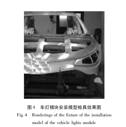

Observing Figure 4 and Figure 5, it can be seen that there is no color difference between the designed headlight module and the connection surface of the adjacent module, and the matching degree is high. From the appearance point of view, the customer’s body is exactly in line with the shape of the module. The interchangeability between real car lights and modules is better, and the overall design scheme is more reliable.
#5 Conclusion
The design of the headlight detection module of the main vehicle model inspection tool is mainly carried out on the structural design of the headlight module, the processing operation arrangement, the manufacturing process and the numerical control processing procedure, etc., and according to the manufacturing standard of the headlight module. Process parameters are designed. The test results show that the headlight detection module fully conforms to the shape of the customer’s body, and supports the mutual conversion between real headlights and modules.